
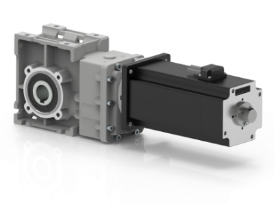
BLDC Traction helical bevel gearmotors series CMB
The main features of CMB brushless DC helical bevel gearmotors range are:
- Low voltage power supply 24/48 Vdc
- Motor protection IP65
- Motor torque ratings available from 0.7 Nm up to 4.2 Nm
- Permanent sinthetic oil long life lubrication
- Die-cast aluminium housing
- Ground-hardened helical gears
- Available motor assembling with coupling system or clamping system
- Also available with sealing ring, viton input

Classification
GEARBOX
| CMB | 105 | U | 9.2 | 020 |
|---|---|---|---|---|
| Type | Size | Gearbox version | Ratio | Output shaft |
| CMB | 402 502 633 903 |
U FD FS FLD FLS FBD FBS |
See tables | See tables |
MOTOR
| BL070.48.80 | 48V | Encoder |
|---|---|---|
| Type | Voltage | Options |
| BL070.48.80 BL200.48.95 BL400.48.120 |
48V-24V 48V-24V 48V-24V |
MEHR 22 HREA 48 |


Lubrication and temperature
Permanent synthetic oil long life lubrification (viscosity grade 320) on CMB gearmotors.
Ambient temperature 0 ÷ 40 °C (in the absence of freezing and condensation).
For temperature outside this range please contact our technical dept.
Radial loads

| n2 [min-1] |
R2 [N] | |||
| CMB 402 | CMB 502 | CMB 633 | CMB 903 | |
| 400 | 905 | 1116 | 1835 | 2682 |
| 300 | 996 | 1228 | 2020 | 2952 |
| 200 | 1141 | 1406 | 2312 | 3379 |
| 170 | 1204 | 1484 | 2441 | 3567 |
| 140 | 1414 | 1743 | 2604 | 3806 |
| 100 | 1582 | 1949 | 2913 | 4686 |
| 90 | 1638 | 2019 | 3321 | 4853 |
| 60 | 2047 | 2490 | 3801 | 5556 |
| 40 | 2524 | 3029 | 4492 | 6614 |
| 30 | 2778 | 3334 | 5159 | 7540 |
| 20 | 3180 | 3816 | 5906 | 8631 |
| 15 | 3500 | 4200 | 6500 | 9500 |
| 10 | 3500 | 4200 | 6500 | 9500 |
When the resulting radial load is not ap- plied on the centre line of the shaft it is necessary to calculate the effective load with the following formula:


a,b = values given in the table
| CMB | ||||
| 402 | 502 | 633 | 903 | |
| a | 86 | 104 | 118 | 157 |
| b | 66 | 79 | 93 | 117 |
| R2MAX | 3500 | 4200 | 6500 | 9500 |
| MODEL | Poles | Phases | Rated Voltage |
Rated speed |
Rated torque |
Rated power |
Peak torque |
Rated current |
|---|---|---|---|---|---|---|---|---|
| [V] | [min-1] | [mNm] | [W] | [Nm] | [A] | |||
| BL070.48.80 | 8 | 3 | 48 | 4350 | 0.7 | 320 | 2.1 | 12 |
| 24 | 2500 | 185 |
| MODEL | Peak current |
Line to line resistance |
Line to line inductance |
Torque constant |
Back EMF |
Rotor inertia |
Weight |
|---|---|---|---|---|---|---|---|
| [A] | [Ω] | [mH] | [Nm/A] | [V/kRPM] | [gcm2] | [kg] | |
| BL070.48.80 | 36 | 0.072 | 0.304 | 0.059 | 6.15 | 1000 | 1.8 |
| MODEL | Poles | Phases | Rated Voltage |
Rated speed |
Rated torque |
Rated power |
Peak torque |
Rated current |
|---|---|---|---|---|---|---|---|---|
| [V] | [min-1] | [mNm] | [W] | [Nm] | [A] | |||
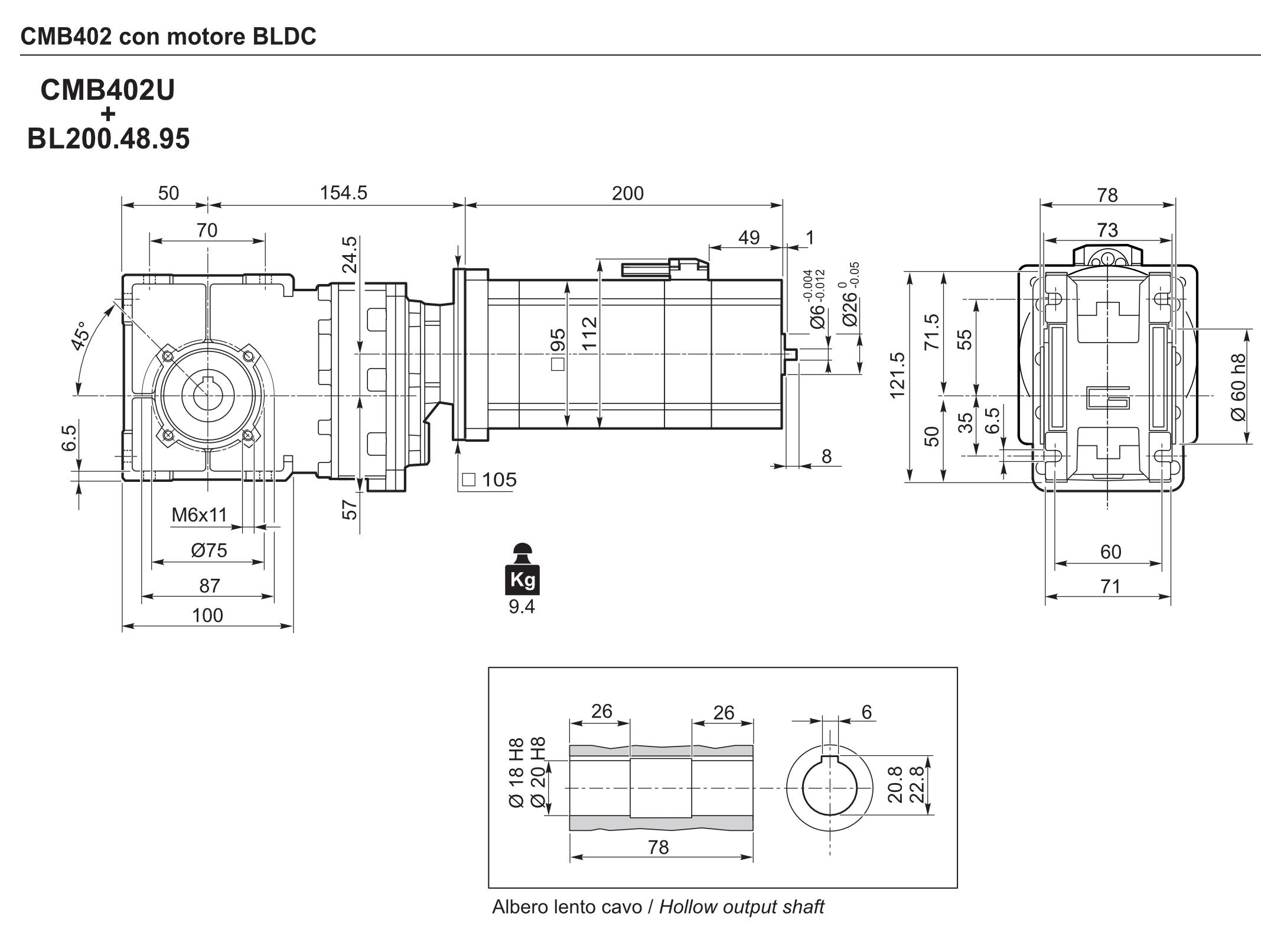
| BL200.48.95 | 8 | 3 | 48 | 3000 | 2.0 | 650 | 6 | 23 |
| 24 | 1500 | 300 |
| MODEL | Peak current |
Line to line resistance |
Line to line inductance |
Torque constant |
Back EMF |
Rotor inertia |
Weight |
|---|---|---|---|---|---|---|---|
| [A] | [Ω] | [mH] | [Nm/A] | [V/kRPM] | [gcm2] | [kg] | |
| BL200.48.95 | 69 | 0.077 (+/-15%) | 0.228 | 0.091 | 6.7 (+/-10%) | 2820 | 6 |
| MODEL | Poles | Phases | Rated Voltage |
Rated speed |
Rated torque |
Rated power |
Peak torque |
Rated current |
|---|---|---|---|---|---|---|---|---|
| [V] | [min-1] | [mNm] | [W] | [Nm] | [A] | |||
| BL200.48.95 | 8 | 3 | 48 | 3000 | 2.0 | 650 | 6 | 23 |
| 24 | 1500 | 300 |
| MODEL | Peak current |
Line to line resistance |
Line to line inductance |
Torque constant |
Back EMF |
Rotor inertia |
Weight |
|---|---|---|---|---|---|---|---|
| [A] | [Ω] | [mH] | [Nm/A] | [V/kRPM] | [gcm2] | [kg] | |
| BL200.48.95 | 69 | 0.077 (+/-15%) | 0.228 | 0.091 | 6.7 (+/-10%) | 2820 | 6 |
| MODEL | POLES | PHASES | SERVICE | Rated Voltage |
Rated speed |
Rated torque |
Rated power |
Peak torque |
Rated current |
|---|---|---|---|---|---|---|---|---|---|
| [V] | [min-1] | [mNm] | [W] | [Nm] | [A] | ||||
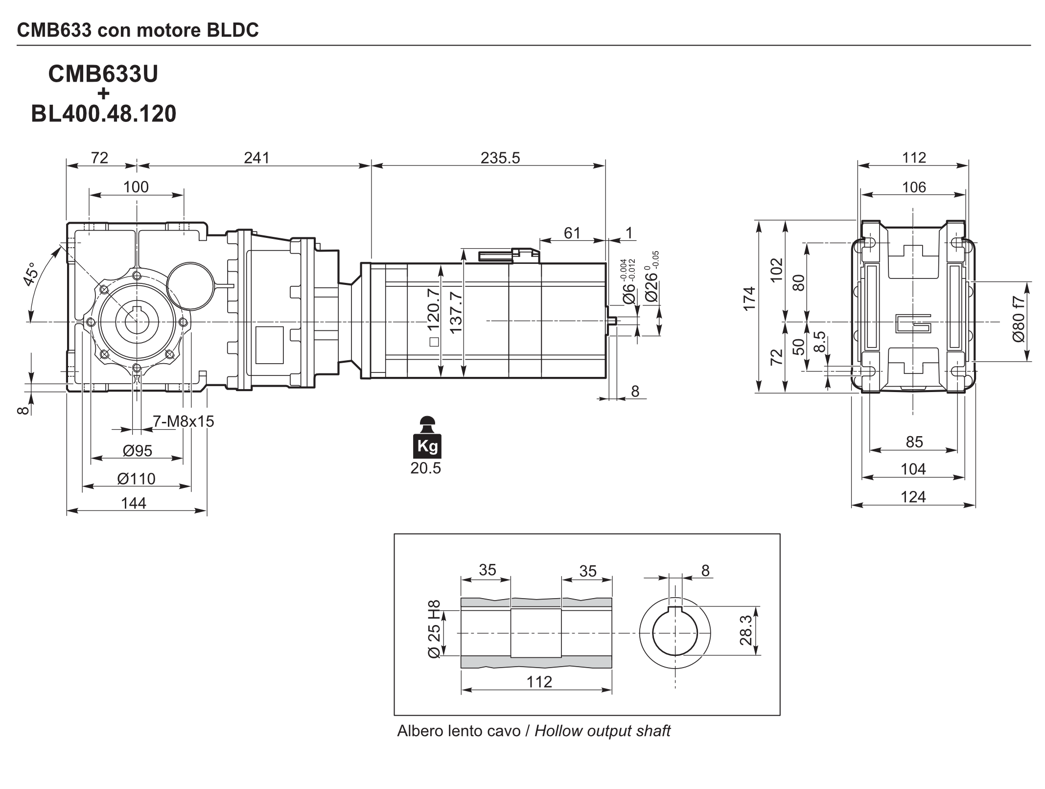
| BL400.48.120 | 8 | 3 | S3 | 48 | 3000 | 4.2 | 1320 | 12.6 | 33 |
| S1 | 3.5 | 1100 | 10.5 | 28 | |||||
| S3 | 24 | 1400 | 4.2 | 615 | 12.6 | 33 | |||
| S1 | 3.5 | 615 | 10.5 | 28 |
| MODEL | Peak current |
Line to line resistance |
Line to line inductance |
Torque constant |
Back EMF |
Rotor inertia |
Weight |
|---|---|---|---|---|---|---|---|
| [A] | [Ω] | [mH] | [Nm/A] | [V/kRPM] | [gcm2] | [kg] | |
| BL400.48.120 | 99 | 0.064 | 0.31 | 0.120 | 12.6 | 21380 | 11 |
| 84 | |||||||
| 99 | |||||||
| 84 |
| MODEL | POLES | PHASES | SERVICE | Rated Voltage |
Rated speed |
Rated torque |
Rated power |
Peak torque |
Rated current |
|---|---|---|---|---|---|---|---|---|---|
| [V] | [min-1] | [mNm] | [W] | [Nm] | [A] | ||||
| BL400.48.120 | 8 | 3 | S3 | 48 | 3000 | 4.2 | 1320 | 12.6 | 33 |
| S1 | 3.5 | 1100 | 10.5 | 28 | |||||
| S3 | 24 | 1400 | 4.2 | 615 | 12.6 | 33 | |||
| S1 | 3.5 | 615 | 10.5 | 28 |
| MODEL | Peak current |
Line to line resistance |
Line to line inductance |
Torque constant |
Back EMF |
Rotor inertia |
Weight |
|---|---|---|---|---|---|---|---|
| [A] | [Ω] | [mH] | [Nm/A] | [V/kRPM] | [gcm2] | [kg] | |
| BL400.48.120 | 99 | 0.064 | 0.31 | 0.120 | 12.6 | 21380 | 11 |
| 84 | |||||||
| 99 | |||||||
| 84 |
Dimensioni


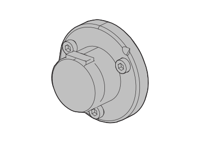
Accessories
Output shaft

| d h7 |
B | B1 | G1 | L | L1 | f | b1 | t1 | |
|---|---|---|---|---|---|---|---|---|---|
| CMB402 | 18 | 40 | 43 | 78 | 128 | 164 | M6 | 6 | 20.5 |
| CMB502 | 24 | 50 | 53.5 | 92 | 153 | 199 | M10 | 8 | 28 |
| CMB633 | 25 | 50 | 53.5 | 112 | 173 | 219 | M10 | 8 | 28 |
| CMB903 | 35 | 80 | 84.5 | 140 | 234 | 309 | M12 | 10 | 38 |
Torque arm

| K1 | G | KG | KH | R | |
|---|---|---|---|---|---|
| CMB402 | 100 | 14 | 31 | 10 | 18 |
| CMB502 | 100 | 14 | 38 | 10 | 18 |
| CMB633 | 150 | 14 | 47.5 | 10 | 18 |
| CMB903 | 200 | 25 | 56.5 | 20 | 30 |
Options
SC – Safety cover

| M | |
|---|---|
| CMB402 | 54.5 |
| CMB502 | 62.5 |
| CMB633 | 73 |
| CMB903 | 94 |
WD – Kit washdown cover

| M | |
|---|---|
| CMB402 | 55.5 |
| CMB502 | 63.5 |
| CMB633 | 71.5 |
| CMB903 | 95 |
Description
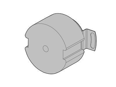
The MEHR 22 is a optical magnetic incremental encoder; he is a reliable hollow shaft encoder and can be fixed in a different sizes of electric motor.
This encoder is developed for brushless motor, motor feedback and the rotazional speed control.
The encoder MEHR 22 is a real time system for speed and position application.
This encoder provide two square wave outputs in quadrature (A-B 90° degrees) for the direction and counting information and a third channel with lap pulse (zero mark).
Additional there is a magnetic encoder integrated which provide UVW signal as commutation. The resolution of encoder is determined by the number of cycles for revolution (CPR).
Power supply and signals are provided by a 11 pin JAE connector.
Main specifications:
- Output channels encoder: A-B-I and /A-/B-/I
- Optional channels hall sensor: U-V-W and /U-/V-/W
- Output type: Line Driver/TTL/RS-422
- Resolution encoder: 2000 CPR (Cycles Per Revolution)
- Resolution hall sensor: 8 pole
- Frequency: 400kHz short cable (<1m), typical 180kHz @2.000cpr -> 5.400 min-1
- Power supply: 5 VDC
- Small size: 39.0 mm (diameter) x 20.1 mm (lenght)
- Operating temperature: -40°C to +100°C
- Compliant EU-directive 2011/65/65/EU and 2015/863/EU
Description
HREA 48 is an encoder optical hall sensor with hollow shaft.
This encoder is specially developed to have a low cost and to work for AGV applications, where precision and speed are essential.
The encoder provide two square wave outputs A and B and their negative outputs /A-/B, The signal I and his negative /I represent the “ZERO” notch, the use of the hall sensors with 8 pole U-V-W and it’s negative /U-/V-/W allows a high precision and control.
Power supply and signals are provided by the braided cable 14Pin 100cm.
Main specifications:
- Output channels encoder: A-B-I and /A-/B-/I
- Optional channels hall sensor: U-V-W and /U-/V-/W
- Output type: Line Driver/TTL/RS-422
- Resolution encoder: 2000 CPR (Cycles Per Revolution)
- Resolution hall sensor: 8 pole
- Frequency: 300 Khz
- Power supply: 5 VDC
- Small size: 48,0 mm (diameter) x 37,0mm (lenght)
- Operating temperature: -40 °C to +85 °C.
- Compliant EU-directive 2011/65/65/EU and 2015/863/EU
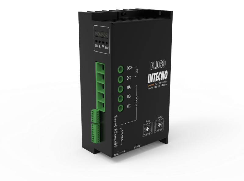
Summary
BLD60 Digital BLDC motor driver is a closed-loop speed controller, which uses IGBT and MOS power, uses the Hall signal of the DC brushless motor to perform double-loop speed control, and has a PID speed regulator in the control link. The system control is stable and reliable.
It can always reach the maximum torque at low speed, and the speed control range is 150 to 4000rpm. The driver use the protocol Modbus RS485 RTU to comunicate in a network.
Features:
- PID speed, current double loop regulator
- 20KHZ chopper frequency
- Electrical stop to ensure the quickly action
- Fault alarm function with Over voltage, Under voltage, Over current, Over temperature, and Hall signal illegal.
Set up
| MOTOR | ENCODER | DOWNLOAD SETUP |
|---|---|---|
| BL070.48.80 | HREA48 | Download PDF |
| BL070.48.80 | MEHR22 | Download PDF |
| BL200.48.95 | HREA48 | Download PDF |
| BL200.48.95 | MEHR22 | Download PDF |
| BL400.48.120 | HREA48 | Download PDF |
| BL400.48.120 | MEHR22 | Download PDF |
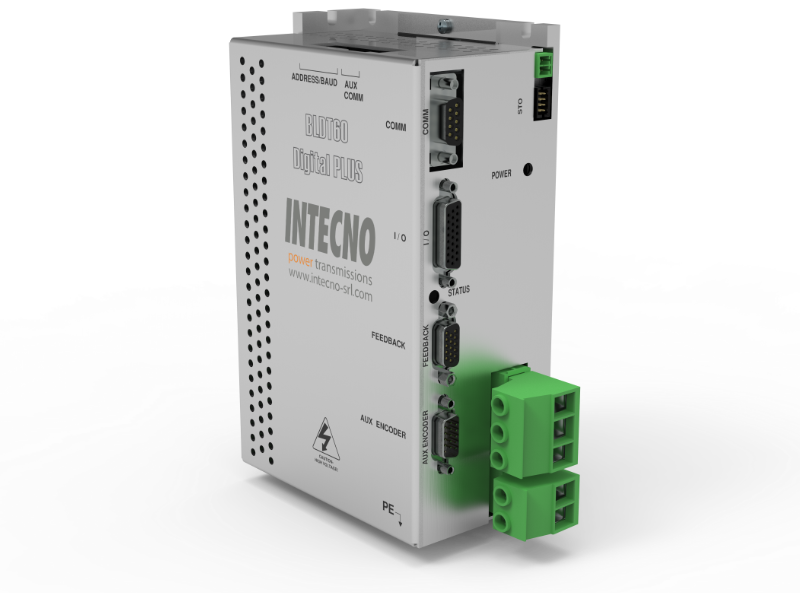
Summary
The BLD60 DIGITAL PLUS servo drives is a fully digital drives operate in torque, velocity, or position mode and employ Space Vector Modulation (SVM), which results in higher bus voltage utilization and reduced heat dissipation compared to traditional PWM. The drive can be configured for a variety of external command signals. Commands can also be configured using the drive’s built-in Motion Engine, an internal motion controller used with distributed motion applications. In addition to motor control, these drives feature dedicated and programmable digital and analog inputs and outputs to enhance interfacing with external controllers and devices.
Network communication is accomplished using either RS-485/232 or Modbus RTU.
Features:
- Four Quadrant Regenerative Operation
- Space Vector Modulation (SVM) Technology
- Fully Digital State-of-the-art Design
- Programmable Gain Settings
- Fully Configurable Current, Voltage, Velocity and Position Limits
- PIDF Velocity Loop
- PID + FF Position Loop
- Compact Size, High Power Density
- 16-bit Analog to Digital Hardware
- On-the-Fly Mode Switching
- On-the-Fly Gain Set Switching
- Dedicated Safe Torque Off (STO) Inputs
Catalog
bevel gearmotors
CMB